Sailboat Hardware Notes
Fancy Free Hardware Kits
General Hardware LocationsNot all parts listed are used, depending on spar option. The parts pertaining to the spar are for a wooden spar, when using the aluminum spar some of these parts will be replaced by spar kit hardware. See spar instructions. Although fastenings are listed for some parts they may not be correct if hardware suppliers change.


1. Gudgeons & Pintles (connect the rudder to the boat; the pintle is the part with the "pin"): Locate pintles on rudder approx. 14" apart, the long pintle on the bottom. Hold rudder to vertical centerline of transom, slip gudgeons all the way onto the pintles and mark screw hole position on transom. Bolt pintles to rudder with 10-24 round head machine screws. Fasten gudgeons to transom with 10-24 machine screws or #10 round head wood screws. The rudder stop (angle) will mount to transom centerline approx. 5/8" above top gudgeon with a #6 round head screw. Do not tighten all the way, it should easily pivot out of the way when the rudder is installed. This piece is meant to keep the rudder from floating out.
2. Sliding Gooseneck (connects the boom to the mast): This fitting will slide on a track at the base of the mast. See #5 Track.
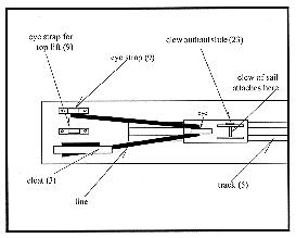
3. Outhaul & Halyard Cleats: OUTHAUL- Use one of the smaller cleats. See Clew Outhaul Diagram on this sheet. BOOM DOWNHAUL-(Small cleat) Used to tension the luff of the mainsail. See #9 Eye strap. HALYARD/TOP LIFT-Locate cleats at a convenient height above base of mast. Peak and throat halyard cleats are located above the #13 Sheave boxes. Use remaining small cleat for the top lift. Used to belay halyards and top lift.
4. Mast Tangs (straps used to attach shrouds to the mast): See Plansheet 4. Through bolt with 1/4" bolts.
5. Track: Cut track: 12" for gooseneck, 6" for boom outhaul. See Plansheet 4 for the location of tracks.
6. Stops: One will be installed on upper end of gooseneck track, one on inboard end of outhaul track.
7. Chainplates (stainless steel straps used for a variety of purposes, in this case, to connect the shrouds to the boat): It will be necessary to drill additional holes in chainplates; should project approximately 1" above deck level. Bolt per instructions, to frame or blocking.
8. Masthead Sheave/sheave axle/plastic divider (the peak and throat halyards ride in these sheaves for raising the main sail and gaff): Mount at the top of the mast per Plansheet 4.
9. Eye strap: See Clew Outhaul Diagram on this sheet for toplift and outhaul. The Downhaul eye strap is used in conjunction with a cleat, much as for the clew outhaul, to haul down on the mainsheet gooseneck to tension the main sail.
10. Eye Band-2": Drill 3/8" holes in the four
"ears". Locate on bowsprit.
11. Hound strap/halyard block/shackle/1/4"x4" RH MS with nuts:
This varies from Plansheet 1. See Hound Fitting Detail on reverse of this
sheet.
12. Mainsheet fiddle block w/cam and becket, pad eye: For controlling the mainsheet. Install on the port side of the aft deck. Provide blocking beneath deck for the pad eye. Although this is a fiddle block, you will only use the lower sheave. See Plansheet 1 for a diagram of the mainsheet layout.
13. Sheave Box (2 each): These are exit blocks for internal halyards. Mount on each side of the mast as shown on Plansheet 4. Plansheet 4 shows two additional sheave boxes (used for the internal jib halyard). We have substituted the optional external jib halyard as it has been preferred by previous builders. See #11 for external halyard block.
14. Swivel Stand-up blocks on Deck Plate (for controlling the mainsheet): Mount on the starboard side of the aft deck (blocking required).
15. Fiddle Block: Hangs on the boom bail at the end of the boom.
16. Boom Bail: Mounts on the end of the boom for attaching Fiddle Block (#15). See Plansheet 4 for location.
17. Cheek block: Used for the toplift. Locate in line with upper shroud tangs to prevent top lift from chaffing on shrouds. See Plansheet 4.
18. Pad eye for jib tack: Mount on bowsprit just behind eyeband.
19. Jib blocks/shackle/pad eyes: See Plansheet 1.
20. Bobstay lug/hex bolt/lock nut: See Plansheet 3.
21. Gammon iron: See Plansheet 3. This chainplate bends around the bowsprit and is bolted through the stemhead. Drill 5/16" holes in chainplate for bolts.
22. Luff groove gooseneck for gaff: Connects gaff to mast. The eye on the gooseneck will be facing up. The throat halyard attaches to this eye. To raise the main: The gaff gooseneck will be inserted into the luff groove, the peak halyard is attached to the opposite end of the gaff, both halyards are pulled simultaneously.

23. Clew outhaul slide: See Clew Outhaul Diagram at the right. Used for tensioning foot of mainsail.
24. Fairlead on slide w/track: For jib sheet leads. See "Determining jib sheet lead for locating hardware" from Hardware Notes Index.
25. Pivoting Cam cleat for jib: Location is shown on Plansheet 1, but can vary. Commonly this cam is located at a point "convenient" for handling the jib sheet. Most builders have installed the jib hardware as shown. One builder attached blocking to the coaming and mounted the deck cam cleat at the top of the coaming.
Glen-L marine designs / www.glen-l.com / Boat plans for the home builder