Sailboat Hardware Notes
INSTRUCTIONS FOR SPAR KITS
GENERAL INSTRUCTIONS
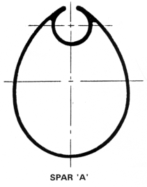
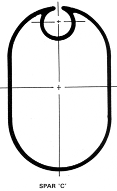
The contents are for each ALUMINUM SPAR KIT are listed on the packing list included with the kit. These instructions and illustrations describe how each fitting is assembled and fitted to the spar extrusion. Fastenings are packed with the particular fitting. In many cases, stainless steel self-threading screws are used for fastening the fittings to the aluminum spar. These require a lead hole of 5/32" in the spar and an 11/64" hole through the castings. Lubricate the screw threads with oil or grease before driving. If tension builds up too much while driving, back the screw out and enlarge the hole slightly to avoid twisting off the head of the screw.
The spars and booms are supplied in standard lengths and may need to be trimmed for some designs. Check the length listed in the plans against the extrusion supplied. To trim, mark where the extrusion is to be cut, wrap with masking tape along the line to help make a square cut, and cut with a hack saw. Finish with a file and emery paper.
To relieve the luff-groove for the sail bolt rope, and for the entry of the gooseneck fitting, place masking tape on the spar approximately 1/4" to each side of the groove and slightly longer than the portion to be relieved. With a "bastard" (very coarse) file, remove the aluminum material by filing across the groove. File to the edge of the masking tape, or to the 1/4" point. Then with a small file or rotary grinder, remove the rough edges of the aluminum inside of the groove. Do NOT cut a-way the groove excessively. Check the end of the spar section to determine the proper amount of material to be removed. Finish the relieved area with emery paper or 100-grit sandpaper so the edges are smooth and round. Sharp edges must be eliminated to prevent excessive wear on the sail. (See page 6 regarding determining position of the groove.)
Refer to the plans of the boat for the proper positions of the various fittings such as mast tangs. The positions of the fittings will vary with the length of the stays and length of the tangs. Thus, it is best to tape the tangs in place where shown in the plans, attach the stays, and check the lengths to the deck fittings. Shroud turnbuckles or shroud adjusters should be adjusted to the midpoint. The turnbuckles or shroud adjusters on the shrouds will provide considerable adjustment, but it is preferable to check the position of the tang before fastening in place and vary accordingly. The castings furnished should be filed and sanded to remove all rough surfaces and sharp edges that could cause wear and chafe on the sails, halyards, and sheets, and also to prevent injury.
END CAP OR FIXED MAST STEP
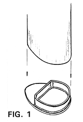
The end cap (see FIG. 1) is an aluminum casting fastened to the mast or mounted on the boat as a mast step. The end cap is not used with the internal stiffener or with the pivoting mast step. For boats 'which will remain for long periods with their masts stepped on the end cap when used as a fixed mast step, a hole should be drilled in the bottom of the fitting or through the 'de as close to the bottom as possible for drainage of water. Such a hole should be minimal in size so as not to weaken the fitting.
When using the fitting as a fixed mast step, the casting should be made a looser fit inside the mast so it slips in place firmly, but easily. As a mast step, the end cap may be fastened to the keel, deck, cabin top, or other position with screws, however, through bolting is preferable. Keep the fitting well waxed or greased so it 'II slip in and out of the mast easily. Do NOT use metal screws to fasten the end cap to the extrusion when it is being used as a mast step, nor use these screws to mount the step to the boat.
PIVOTING MAST STEP (TABERNACLE)
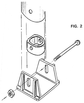
The pivoting mast step (if furnished) has a bolt passing through the fitting and the mast for the mast to pivot on to simplify raising and lowering the mast. Note that once erected vertically the mast rests directly on the pivoting mast step, and NOT on the bolt. This means that in some cases filing of the mast at the base 'II be required to assure that the mast mates firmly to the mast will be required to assure that the mast mates firmly to the mast step, fitting at all points and does not just rest on one corner due to mast rake and other variables in mast angularity.
For some boats using the "A" section, an internal stiffener (See FIG. 2) with metal screws is provided. End caps are not used with pivoting mast steps. The internal stiffener (if provided) is filed as required for a firm fit inside the mast at the base. Coat the stiffener with oil and drive it flush with the bottom of the mast. Use the metal screws, one on either side, to secure the stiffener inside the mast. The screws should be located toward the forward portion of the mast so as not to interfere with pivoting of the mast in the mast step fitting.
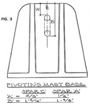
The pivoting mast step requires a slot cut in each side per dimensions noted on FIG. 3 to suit the spar section being used. This can be done by drilling a series of holes, filing out between, and sanding or filing the edges smooth. Position the base of the mast into the step and mark for the pivot bolt holes so that there is approximately 1/16" clearance between the bolt and the bottom of the groove in the step. Drill from both sides and align the holes as carefully as possible. Insert the bolt through the fitting and the mast, and try pivoting the base. If necessary, radius the aft end of the spar slightly so that the mast will pivot easily, yet still bears firmly to the mast step. It is important that the base of the mast bear directly onto the pivoting mast step fitting. File the fitting if necessary to assure a firm fit.
HOUND FITTING-SPAR "A"
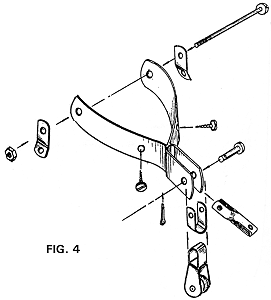
This hound (see FIG. 4) consists of a fitting that wraps partially around the mast, two tangs, a bolt, and metal screws. When a jib IS NOT used, the hound is furnished with a pin and a toggle for the forestay. When a jib IS used, the hound is supplied with a shackle and block for the jib halyard in addition to the toggle. The bolt used for fastening the hound in place may also be used for bolting the mast tangs to the mast.
Temporarily tape hound in place, attach the forestay, and check location before drilling any holes. Place the hound firmly on the mast and mark the holes required on either side. Center punch and drill from each side. Bolt the hound and mast tangs through the mast, and then fasten the hound to the spar with the metal screws. On some boats, the tangs are located above or below the hound fitting and an additional bolt is furnished.
HOUND FITTING-SPAR "C"
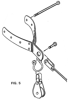
This hound is similar to that provided for SPAR "A", but is larger (see FIG. 5). Use a bolt through the aft holes plus metal screws (or comparable fastenings) through the other holes. Note that it may be necessary to re-drill the holes oversize to suit the fastenings. The bolt used to mount the hound may or may not be used to fasten the tangs. An extra bolt will be provided if the tangs are to be located either above or below the hound for the shrouds. The forestay attaches to the hound via a toggle-type fork secured by the pin of the supplied shackle, which passes through the eye of the hound. A jib halyard block may also be secured to this shackle.
SPREADER ASSEMBLY
Spreaders are used to reinforce the mast and may vary with the design. For boats having diamond-type spreaders, these are noted elsewhere in the instructions.
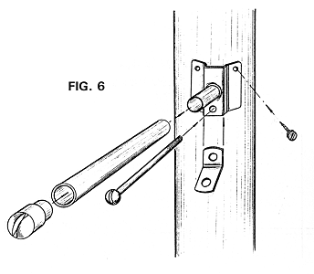
The type of spreader assembly and its installation will vary with the design. In general, the spreaders consist of spreader fittings which attach to the mast, a spreader tube which mates to each spreader fitting, and spreader tips which fit into the ends of the spreader tubes to receive the upper shrouds. Additional fittings, such as tangs, may be included as required. See FIG. 6 & FIG. 7.
The location of the spreader assembly may be taken directly from the plans for the boat; however, minor variations may be required depending on how the chainplates are mounted and the length of the mast tangs. The position of the tangs on the mast should therefore be checked to be sure the shrouds would fit. This will mean erecting the mast on the boat to the proper position and rake, and clamping or taping the tangs temporarily in place.
Check the distance from the chainplate eyes to the tangs so they are equal in length on either side, and equal to the length of the shroud when adjusted to the midpoint. The turnbuckles or shroud adjusters on the shrouds will provide considerable adjustment, but it is preferable to check the position of the tang before fastening in place and reposition if necessary.
The center of the spreader fitting should be positioned on either side of the mast so they are directly opposite one another. This can be determined by hooking a flexible measuring tape in the mast groove and measuring around the mast.
For the SMALL FIXED SPREADER FITTING (FIG. 6), center punch each side for the through-bolt and using the appropriately sized drill, drill from both sides. The mast tangs are placed under the spreader fitting on each side of the mast. The bolt extends through the mast holding both the spreader fittings and tangs in position. Avoid over-tightening the through-bolt to prevent compressing the mast. Use the metal screws provided to secure the fitting to the mast.
Fit the spreader tubing into the spreader fitting. A screw or clevis pin may be used to secure the spreader tubing to the spreader fitting. Insert the spreader tips into the ends of the spreader tubes and glue or fasten in place. If further adjustments are required, minor trimming of the spreader tubes may be done so that the shrouds will fit precisely with proper tension. Note that the lengths of the spreaders are given on the plans; some trimming of the spreader tubing may be required. Take care when checking this dimension since it may be given from the boat's centerline; AND may also include the spreader tip in the dimension. Vary the tubing length accordingly.
Lashing or taping the shrouds to the spreader tips is advisable. This will prevent the shrouds from falling out of their grooves should the shroud become slack on the leeward side.
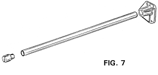
For LARGE FIXED SPREADER FITTING (see FIG. 7) used on SPAR "C", the casting is fastened to the side of the mast only with sheet metal screws or comparable fastenings; this fitting is NOT bolted nor are the shrouds attached to it. Instead, a separate bolt is provided for the shroud tangs, which will be located an inch or two below the castings (varies with shroud length). Either single or double tangs may be provided depending on the design. Spreader tips are otherwise similar to that previously described.
IMPORTANT- With all spreader fittings, if the spreader fitting is of the splayed or angled type, locate the fitting so that the spreaders will rake UPWARDS.
DIAMOND SPREADERS
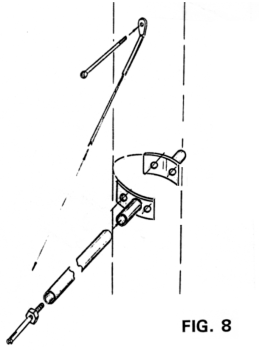
Diamond spreader kits (FIG. 8) using a single or double set of spreaders may be provided to reinforce the mast. The assembly consists of the diamond spreader fitting(s), spreader tubing, metal screws, and adjustable spreader tips for tensioning the diamond stays. The diamond stays provided have swaged terminal fittings and bolts for fastening to the mast.
The wire rope stay is bolted through the mast just under the mast tang for single fitting installations. When two spreader fittings are provided refer to the plans for location. The spreader fitting in the single spreader assembly is located at the mid point of the spreader wire. See the Fig. 9 for dual spreader fitting locations. Put the fitting on the mast and drill the three metal screw holes with a 5/32" drill and install. Fit the spreader tubing onto the diamond spreader fittings and insert the adjustable spreader tips into the end of the tubing, threaded all the Way in. Pull the spreader wires taught, through the spreader tip, locate and drill the hole for the bottom through bolt and fasten.
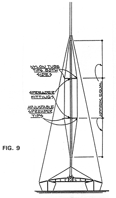
The mast should be adjusted with the stays so that it is straight when sighting along the spar. The stays should be tight to prevent bending of the spar, but do NOT over-tighten them. If necessary, the end of the spreader tubing may be trimmed off slightly to provide more adjustment. However, the lengths of the two pieces of tubing opposite one another should be equal. After adjusting the spreaders and setting the stay tension, the adjusting nut head should be wrapped with tape to prevent chafing the sail.
If double diamond spreaders have been provided, note that the upper set of spreaders will be fitted with fixed spreader tips (see FIG. 9). The lengths of the spreaders with the adjustable spreader tips should be within plus-or-minus 112" of the length of the upper spreaders. Diamond spreaders should be checked from time to time to assure proper tension. It is advisable to wire or pin the stays to the spreader tips.
NOTE - If the stay tension is allowed to loosen, and the wire come out of the tip on the leeward side; the mast may fall when you come about.
GOOSENECK FOR WOOD BOOM
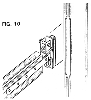
The gooseneck fits into the luff-groove of the aluminum mast (See FIG. 10). The position of the relieved area of the mast for inserting the gooseneck is best obtained by stretching the sail along the mast (see heading "GENERAL INSTRUCTIONS" for further details). Hold the top of the sail 6" to 8" lower than the top of the mast and stretch the boltrope at the luff tightly along the mast.
Mark the groove at the tack corner of the sail. The portion 8" to 12" above this point is relieved both for the entry of the gooseneck into the luff-groove and also for installing and removing the sail. The gooseneck, in turn, fits to the boom with a downhaul being used to prevent the gooseneck from sliding up and out of the slot when under sail. For boats with wooden booms, the boom is made as detailed in the plans for the particular design.
ROLLER REEFING BOOM COMMENTS & OPERATION
If ROLLER REEFING GOOSENECK and OUTHAUL fittings have been provided, there use is optional. Other reefing methods can be readily adapted by the builder if desired. If the ROLLER REEFING BOOM is used, the sail is furled or rolled onto the boom in order to decrease sail area in strong winds. To reef the sail, head the boat into the wind and luff the sail. Release the main halyard until the desired amount of sail has been furled onto the boom. Then let the boom spring forward and lock into place. Re-tension the halyard and continue sailing.
GOOSENECK FOR ROLLER REEFING BOOM
The roller reefing gooseneck assembly (FIG. 11) includes a cast aluminum fitting that fits into the forward end of the boom, a gooseneck that slips into the mast luff-groove, metal screws, and a bolt with large 3/8" washer and wing nut.
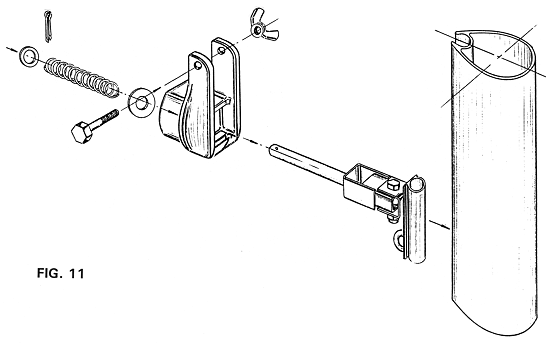
First drill a 3/8" hole in the forward pocket-like cavity through the aluminum casting (a "dimple" for the drill is provided in the cavity for positioning). In this same fitting, drill an 11/32" hole through the two upright legs 3/4" down from the top and 1/2" in from the sides for the bolt and wing nut. Then round the edges of the legs by filing so they will not chafe the sail.
Assemble the gooseneck fitting to the casting as follows: Remove the cotter pin, small washer, and spring from the fitting. Then push the shaft of the fitting through the forward side of the hole drilled in the aluminum casting. The squared portion on the gooseneck fits into the pocket cavity in the aluminum casting. Slip the large 3/8" washer onto the gooseneck shaft and set it against the backside of the casting. Then assemble the spring with washer and cotter pin as it was originally. Considerable pressure is required to compress the spring in order to insert the cotter pin.
The assembly is to fit into the end of the boom extrusion in a tight or "jam" fit. However, prior to this, the slot on the boom should be cut away a distance of 8" aft of the forward end of the boom for the entrance of the foot boltrope of the sail. Also, the gooseneck is designed to fit into the luff-groove of the mast extrusion. See headings "GENERAL INSTRUCTIONS" and "GOOSENECK FOR WOOD BOOM" for further details. The sail tack (lower forward corner) is secured between the casting legs by the bolt with wing nut.
OUTHAUL FOR ROLLER REEFING BOOM
The outhaul fitting consists of an aluminum casting, a bolt with self-locking nut, metal screws, and a boom tang. The casting is to fit into the aft end of the boom. To do this, widen the slot on the boom by filing, and cut another slot in the aft end of the boom along the bottom of the boltrope groove about 1/4" wide and 1-1/4" long (see FIG. 12). This cut should be filed for a tight "jam" fit of the casting into the end of the boom. Drill a 13/32" hole through the casting at the boss (raised portion) on the aft side of the casting. Drill two holes of the same diameter through the upright portion of the fitting. Position these holes 1/2" down from the top and 1/2" in from the ends.
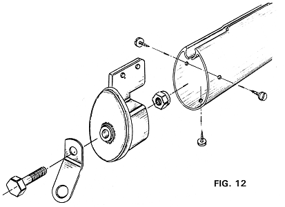
Assemble by bolting the boom tang to the aluminum casting with the self-locking nut on the inside. Do NOT tighten the bolt excessively, but leave it loose enough so the boom tang will pivot freely. Although the self-locking nut will not usually unwind, it is advisable to center punch the threads at the nut to prevent the unit from working free.
Fasten the aluminum casting into the end of the boom with three metal screws, one on each side and one at the bottom of the boom. The two holes in the upright portion of the fitting can be used for the clew outhaul of the sail. File these two holes smooth so they won't chafe the line. The sail may be shackled directly to these holes or the clew outhaul may be used through one of the holes and then to a cleat located on the boom to suit. While the two holes allow for some adjustment, a separate sliding luff groove fitting can also be used if desired, similar in arrangement to the gooseneck downhaul.
MASTHEAD FITTING FOR JIBHEAD RIGS
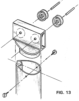
This fitting (see FIG. 13) can be used for external or internal halyards. The assembly consists of an aluminum casting, two sheaves, rivet axles, and metal screws.
For an external halyard, center punch and drill a hole to fit the aluminum rivets 3/8" in from the ends and 1" down from the top. Because of the slightly tapered sides of the casting, it is preferable to drill the holes for the two-sheave rivets from both sides rather than attempting to go straight through. Slip the rivets through the holes with the sheaves inside. To hold the rivet in place, use a countersink and "dimple" the end. File the fitting so it will slip inside the top of the spar. Fasten with two metal screws, one on each side of the mast. Relieve any sharp edges on the casting that may rub against the halyard.
This same fitting may also be used for an internal halyard. In this case, the position of the sheaves must be altered. The sheave on the aft end is located 3/8" in from the aft end, and the forward sheave 1-3/4" in from the aft end. Both are centered 1" down from the top of the casting. When an internal halyard is used, a FAIRLEAD or SHEAVE BOX is required near the base of the mast for the exit of the halyard.
MASTHEAD FITTING-SPAR "A"
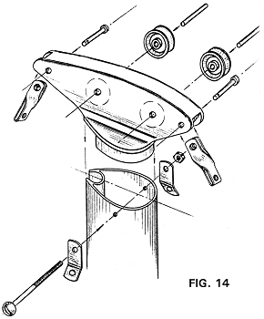
The masthead fitting consists of an aluminum casting, sheaves, sheave axles, clevis pins and cotter keys, toggles, a tang bolt with nut, mast tangs, and metal screws (see FIG. 14).
First file all burrs from the casting, particularly where the halyards will ride. Holes through the casting for the internal halyards should have edges well rounded and smooth. Fit the casting into the top end of the mast in such a manner that the flange fits flush to the top of the mast. This will require filing the casting to eliminate the inside radius or "fillet". The fit should be tight, with the casting being driven home by solid taps of a mallet.
Prior to permanently fastening the casting in the top of the mast, drill holes through the casting as indicated on the DRILLING TEMPLATE. This template can be cut out, laid over the casting, and the holes center punched to the casting. After drilling the holes, insert the sheaves into the casting in line with the sheave holes and insert the axles. Peen over the ends to hold the axles in position. Insert the pins through the fore and aft end of the fitting with the toggles in position as shown.
Check to make sure that all halyards will run smoothly through the sheaves and down the slot in the base portion of the casting without hitting any projecting sharp edges. The casting is then slipped into the top of the mast and held in position by the bolt through the top of the mast. This bolt will have tangs attached under the head and nut as shown in FIG. 14. Jam the nut with a center punch so that it will not come off. Drive a metal screw through the mast and into the fitting on the forward side.
MASTHEAD FITTING - SPAR "C"
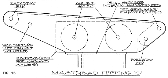
The masthead fitting consists of an aluminum casting, sheaves, bolts serving as sheave axles and pins for the stays, locking nuts, shackle/toggles, a tang bolt with nut, mast tangs, a divider/spacer, and metal screws.
The configuration is shown by FIG. 15. Either external or internal halyards can be used. File all burrs and rough spots from the casting, particularly where the halyards and sheaves ride. If using internal halyards, the fitting may have to be relieved by filing at the hole through the base as well as at the aft edge for the main halyard to run without rubbing against the casting. All edges should be well rounded and smooth.
Fit the casting into the top end of the mast so the flange fits flush to the top of the mast. This will require filing the casting to eliminate the inside radius or "fillet". The fit should be tight, with the casting being driven in with solid taps of a mallet.
Prior to permanently fastening the casting to the top of the mast, drill holes through the casting as indicated by the "dimples" in the side of the casting to suit the axle and pin bolt diameter. Insert the sheaves into the casting with the divider/spacer between and pass the axle bolts through. Install the shackle/toggles similarly, and use the locking nuts to secure the bolts to the casting. Although the nuts are the locking type, it is a good idea to center punch the threads to assure that the nuts will not work free and come off. Recheck and make sure that all halyards will run smoothly without hitting any projecting sharp edges.
The casting is then slipped into the top of the mast and held in position by the bolt through the top of the mast. This bolt will have tangs under the head and nut. Jam the nut with a center punch. Drive metal screws through the mast and into the fitting near the forward and aft areas.
GAFF RIG MODIFICATIONS TO ALUMINUM SPAR KITS
Where a gaff rig is used (such as on the CHESSIE FLYER and FANCY FREE designs) some modifications from the standard SPAR INSTRUCTIONS, as well as from the instructions provided with the plans, are required as follows:
- The jib halyard on the aluminum spar kit is intended for external operation, passing around the jib halyard block attached to the hound fitting on the forward side of the mast, and belaying to a jam cleat on the side of the mast; no sheave box is required for this halyard as may be shown on the plans for the wood mast.
- If a mizzenmast is provided, the peak and throat halyards also run externally with the aluminum spar kit, similarly to the wood spar that may be detailed on the plans. The peak halyard, however, passes through the shackle block on the aft side of the masthead fitting (See the MIZZEN MASTHEAD DRILLING TEMPLATE - GAFF RIG) and down the side of the mizzenmast. The throat halyard may be run internally as noted on the template.
- The OUTHAUL FOR ROLLER REEFING BOOM fitting described elsewhere in the spar instructions shows two holes drilled through the top protruding portion for the clew outhaul. In gaff rig designs, these are not required since clew outhaul slides are provided. The portion of the fitting where these holes would be drilled, however, must be filed off on the aft protruding edge to a radius in order to clear the tang that is attached to receive the topping lift shackle. In lieu of the drawings shown elsewhere for this fitting, there are two such tangs provided for each fitting; one for attaching the sheet blocks, and the other for attaching the topping lift shackles (one tang will point down while the other will point up).
-
The MASTHEAD FITTINGS-SPAR "C" described elsewhere in these
instructions is intended for both masthead rigs and gaff rigs. While
shown elsewhere as a masthead rig, the following describes the changes
required for the gaff rig masthead. Using the drawing in the
instructions as a guide, only the two aft sheaves and divider plate are
provided with GAFF RIG kits, plus one axle. There is no backstay or
forestay attached to the masthead, and no sheaves are required for
headsail halyards in the fitting. The main peak and throat halyards pass
over the one set of sheaves and run internally in the mast as for the
wood spar detailed on the plans, exiting through sheave boxes
below.
NOTE: With gaff rigs, the masthead fittings should be carefully filed and checked to assure smooth, rounded surfaces and corners to minimize chafe and wear of the various halyards.
CLEATS
Cleats are provided to secure lines such as the main and jib halyards, the downhaul line required to prevent the gooseneck from sliding up the mast, or for the clew outhaul line for those SPAR KITS provided with an aluminum boom extrusion.
Locations of these fittings are generally made to suit the individual's desires. Halyard cleats are frequently located near the base of the mast, either on the mast itself or on the adjoining boat's structure (cabin, deck, cockpit, etc.). In some cases on larger boats, halyard winches may be desired, and in this case, the cleats are usually located beyond the winch.
The cleat for the downhaul is located on the mast, below the gooseneck, adjacent to the groove. On larger designs where greater tension is desired for this line, an eye strap or deadeye may be located opposite the cleat with the downhaul dead-ended at the eye strap, then passing up through the gooseneck eye or sail grommet by the tack fitting, and then down to the cleat.
The clew outhaul used with the aluminum boom extrusion is located at any convenient point near the aft end of the boom, which will allow for clew adjustment. In some cases, a clew outhaul slide may be provided and these are used similarly to the gooseneck with a downhaul.
When jam cleats are provided which will be attached to the spars, fastenings are provided. Note that jam cleats are provided for the purpose of belaying a line; not for coiling of the excess line. Cleats for wooden booms are supplied with the HARDWARE KIT.
FAIRLEADS & SHEAVE BOXES
Fairleads and sheave boxes may be provided with SPAR KITS, which include the option of using internal halyards. The fairleads or sheave boxes are used where the halyards exit the mast. Where this feature is optional, the builder must decide if the extra complexity and exposure to chafing inherent with internal halyards is more desirable than the simplicity or external halyards.
For boats with only a mainsail, or for boats having a non-masthead rig, only one fairlead or sheave box is provided, and this is for the main halyard. For masthead rig boats having a main and jib, two fairleads or sheave boxes will be provided, one for each halyard.
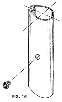
The fairleads may be provided with an adhesive used per the directions on the container. The fairleads are located on the side of the mast near the base and above the cleat, or to suit. A hole is drilled in the mast so the fairlead slips firmly into place (see FIG. 16). Allow the adhesive to dry thoroughly before using.
With sheave boxes, these are usually located on the side of the mast, with the main halyard usually exiting to starboard, and the jib halyard to port. If halyard winches are desired, usually the sheave boxes are located near the mast base with the halyard winches above the exit points on the side of the mast. Optionally, the sheave boxes can be located near the base of the mast leading to various turning blocks located on the deck, cabin top, etc., and then to winches in the cockpit, cabin top, deck, etc.
Determine the size of the hole required in the mast to suit the sheave box and drill holes to suit. Use a file to shape and size the hole to the sheave boxes, and then position in place. Use a center punch to locate the fastenings provided, using fastenings in ALL the holes provided with the fitting. Take care in locating the sheave boxes to assure that the halyards make a "fair" lead to the sheave box and will not foul with internal fittings or with an opposite sheave box.
Glen-L marine designs / www.glen-l.com / Boat plans for the home builder