RC Model X1 Notes
RC and underwater gear used on the test model
SOURCE FOR PARTS
The prototype used components obtained from: DUMAS PRODUCTS INC., 909 East 17th St., Tuscon, AZ. 85719. The part numbers listed and the descriptions are based on their nomenclature; other similar products can be substituted.
PROPULSION SYSTEM
The details given are for powering the RC MODEL X-1 with an electric motor driven by a battery. A gasoline motor could be substituted with modification, but details are not provided. The boat should balance when completed, and float level with the Longi #2 top surface. The major weight, the main battery, may need to be shifted to bring the boat in proper balance. A brief description of the motor and related parts used on the prototype should be added to that under "Underwater Gear" for a complete listing.
- Dumas boat motor - #2025 6V, 10,000 RPM - #2025
- Speed control - #8314 - Dumas SP 520, Hi-tec
- Battery - #8302 - 7.2 Nicad battery pack
- Charger #8315 - Dyna Mega 1 AC/DC Quick charger
- Radio Package - #8812 Includes transmitter, receiver servo, and battery holder.
UNDERWATER HARDWARE

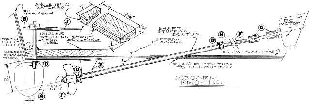
A. Rudder #29279 & #26194: From 1/16" sheet brass with
1/8" diameter shaft slotted for rudder; solder to rudder as shown. Shaft
rotates in a brass stuffing box tube inserted through the boat bottom
1/16". Epoxy in place vertical to transom centerline and right angles to
the longitudinal centerline. Rudder to turn no more than 35 degrees each way
from the centerline.
B. Tiller Arm #3504 - Fits on rudder shaft atop rudder tube. Use washer
"D" between so there is minimal rudder up and down motion.
C. Propeller (prop) #3003 - For 1/8" shaft, slotted on forward side
for matching drive pin. Includes nut to match prop shaft.
D. Nylon thrust washers, 3 rqd. #7019 - For 1/8" shaft; use as
shown at three places
E. Strut #3314 - For 3/16" tube that is fixed in strut; prop shaft
"F" rotates in tube. Flatten boat bottom, bed in thickened epoxy to
match shaft angle, and fasten to blocking with ½" #2 SS, FH or OH
wood screws.
F. Prop shaft #26-193 & stuffing box tube #27=108. Shaft is
1/8" in diameter and rotates inside the 3/16" outer diameter stuffing
box tube. The shaft is threaded for the prop nut and the other end for the
coupler "G". The strut "E" and shaft stuffing tube are
installed simultaneously directly on the centerline. Drill a hole in the boat
bottom, as shown, and elongate it to the correct angle. The distance between
the shaft centerline and boat bottom at the transom is noted. Use these two
points to fix the shaft angle then locate the strut (see "E" above)
and epoxy the cavity around the tube boat bottom with a fillet. To absorb fore
and aft thrust, a nylon washer "D", is inserted between the strut aft
end and prop, and at the tube forward end. Hold in place by Collar
"H" or coupler "G", set screwed to the shaft. Adjust the
shaft end play in the tube to be minimal and still provide resistance free
rotation.
G. Coupler or drive dog #2013 - Connect the prop shaft to the motor
with a universal joint coupler to account for minor misalignment. However,
efficiency is improved if the two shafts are in precise alignment. (see
instructions "MOTOR ALIGNMENT") The coupler is essentially two brass
fittings slotted to accept a nylon drive shaft. The brass fittings are threaded
on the prop shaft and slipped over the motor shaft and held by
set-screws.
H. Collar # 7015 - For 1/8" shaft with set-screw, locks to prop
shaft at forward end of stuffing box tube. (see "F" above)
J. Push rod & EZ connector - #8702 & #8708 - Includes nylon
clevis, connects Tiller "B" to servo.