Hardware: Where to start
An introduction to hardware, based on Chapter 11 from our book INBOARD MOTOR INSTALLATIONS.

Plate 33
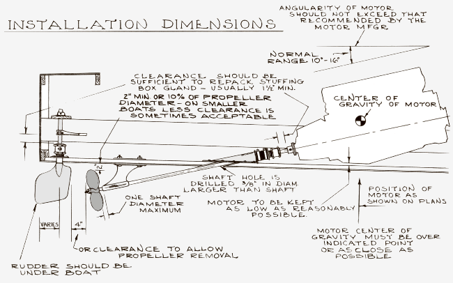
The proper way to determine the accurate position of the various units that constitute the inboard motor installation is to make a full size layout, or a physical substitution or "mockup" of the entire propulsive system. The layout does take time, BUT it is not complicated. The advice is to stick to it and follow through the procedures a step at a time by following the text and illustrations provided.
In the examples shown by Plate 33, a standard planing type boat is used as an example. While there are other straight-line shaft installations that are somewhat different, the principles are similar and can be extrapolated to various types of boats. In the illustration a few standard dimensions and clearances are given for an inboard installation.
With most installations it will be desirable to get the engine as low in the boat as practicable in order to reduce the shaft angle. However practical limitations must be considered. The engine should not be subjected to excessive bilge water, and some clearance is desirable for access to certain motor components.
The position of the rudder can vary with certain designs, while in other cases, the designer provides quite specific size and location requirements for this component. With most boats solid water must be kept over the rudder which means that in most cases the rudder MUST be located under the boat. If placed too close to the transom, air may be sucked into the rudder causing poor steering and loss of control on turns. Sometimes the rudder can be located somewhat outboard from the transom, in which case a plate extended out from the transom over the rudder will cure this problem. It is also possible to set the rudder too far forward which will cause the shaft angle to increase. In general locate the rudder inboard as far as practical and at least so the aft edge of the blade is completely under the boat whenever possible.
The desirable distance between the propeller and rudder is at least 4" or as required to provide room to remove the propeller without first removing the rudder. Clearance between the bottom of the boat and the propeller should normally be at least 2" or 10% of the propeller diameter (see Chapter 9) whichever is least. While it is possible to "cheat" on these clearances somewhat, especially on small boats or other cases where cramped conditions apply, it is best to strive for the minimum tolerances noted for general practice. Then again, on very high-speed competition type boats, the distance from the rudder to the propeller is often increased.

Plate 35
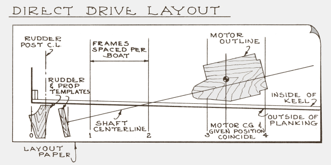
If you have a full size layout of the boat, or are building a boat from lofted lines, the layout for the engine installation can be readily made as illustrated by Plate 35. Failing this, it may be possible to make a full size layout from the boat. The only areas of the hull that are important are the frames from the transom or stem forward, in way of the motor area, and the line of the keel. The outline templates representing the engine, propeller, and rudder may be cut from paper, cardboard, or wood. If no dimensions or drawings of the motor are available, make a rough template taking dimensions directly from the motor, or sketch a rough outline in profile view. The engine shaft centerline is desirable for reference purposes and should be rather accurately pinpointed. The portion above this reference is desirable for checking heights and clearances, but may not be necessary in all cases. In lieu of rudder and propeller templates, the actual rudder or propeller can be used. The width of the propeller can be estimated by dividing the pitch by the number of blades. For example, a propeller with a 12" pitch and three blades would have a width of 4". This is only an approximation, and if possible, the width or hub thickness of the propeller should be checked, or the supplier should have the information.
Plate 35 shows a typical installation drawing. Note that the point where the shaft passes through the boat may be readily found both on the inside and outside of the boat, assuming that the thickness of the hull at this point is fairly closely known. The shaft angle can be found by using a protractor.
Shaft logs and struts come in standard angles, so you will need to adjust the shaft angle on the layout if you intend to use stock parts.
Solar notes
The following is a description of the hardware used on our Amp Eater along with comments re. hardware required for solar competition. Much of the bronze hardware is overkill and heavy for use in solar competition. But these are availble without special fabrication.

Amp Eater Hardware
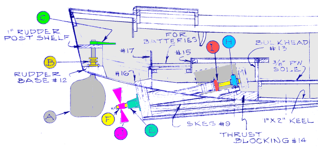
Standard inboard hardware is heavy stuff; having lighter weight components will be an advantage. Above is a drawing of the Amp Eater motor installation. This boat has an external skeg with a tube running through it, sealed by a stuffing box on the inside. The boat is not designed for competition and is used simply to illustrate hardware options.
For classes starting a solar competition, it would probably be a good idea to discuss the various pieces of hardware required, then brainstorm to come up with alternatives that are lighter in weight or more efficient solutions. The "layout" described above should be considered a necessity. You have to know what shaft angle you require before purchasing or fabricating any shaft hardware.
IMPORTANT: If using stock parts, the strut bearing and shaft stuffing box must match the propeller shaft OD. One inch is readily available, there is limited availability for other shaft diameters.
A. Rudder: The Amp Eater used a bronze rudder, which is heavy. Fabricating a rudder of lighter material (aluminum) would be advantageous. The "shaft" diameter of the rudder must match the stuffing box, if one is used. Alternately, a tube (ID must match OD of rudder shaft) that extends above the waterline could be bonded into the hull and the stuffing box eliminated. Something as simple as PVC pipe could be used as long as it matches rudder shaft.
What keeps the rudder from falling out the bottom of the boat? The tiller arm (C) or a safety collar.
B. Rudder Stuffing Box: The rudder stuffing box provides bearing for the rudder and has a seal that keeps water from entering the boat. The "seal-type" would have less friction than the "packing-type", but this is not terribly important.
C. Tiller arm: An arm that is pushed or pulled to turn the rudder. Can be activated by a steering wheel, or simply by a lever and a push-pull cable. The Amp Eater uses ridgid conduit with universal joints at each end.
E. Stern bearing housing: This is mounted on the skeg in-line with the shaft tube. This would be comparable to the strut shown in Fig. 33. The stern bearing housing has a bearing, which supports the shaft. The strut does the same thing. In practice all you really need is a tube held in position that will accept a standard shaft bearing. It would be possible to fabricate a strut by welding aluminum plate and a tube for the bearing. The tube would have to have an inside diameter to match a standard strut bearing.
F. Propeller Shaft A 4' x 1" stainless shaft weighs about 13 lbs. Some groups have used tubing, but this requires provision on on end for the propeller.
H. Thrust bearing (Flange shaft bearing): This takes the thrust of the propeller and provides support at the motor end.
I. Shaft Stuffing Box: The stuffing box shown in the Amp Eater drawing is inserted in a a hose and clamped to the shaft tube. The more common option uses a shaft log. The angle will be determined from the layout. Aluminum being first choice for the log. The seal-type stuffing box will have less friction than the packing-type.
J. Propeller: Bronze propellers are overkill for a solar competition project... but are readily available. If using a used propeller, it should be check to see it is in balance, with no bent blades. Some teams have used composition propellers, purchased from electric boat manufacturers.
Motor: The Amp Eater used a Pacific Scientific, 24 volts DC, 1 hp motor, mounted on a pivoting mount (for adjusting tension). There is a pulley on the motor and propeller shaft, with the motor mounted parallel to the propeller shaft. There is a belt between the two pullies. The motor can also be mounted "in-line", but this could put the motor up too high and too far forward. (For more information about parts used on the Amp Eater, see Amp Eater Notes.)
In discussing the competition with various teams, the emphasis has been on three things:
1. Balance of the boat. This really requires getting the boat in the water and testing it, which means the boat has to be ready early enough that there is time for testing.
2. Weight. Keeping the components as light as possible.
3. Reducing friction on the prop shaft. At college level competition, some teams have used ball-bearing or roler-bearing for the prop shaft. This probably means that the strut must be custom made.