Continued from WebLetter 12
Page 4 of 4
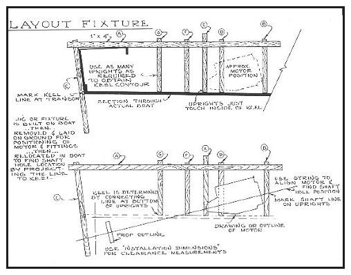
 Plate 38 - This layout can be
used to make the shaft and motor layout in an existing boat.
If the hull has been built or already exists, and full size drawings are not available, another simple method for determining the shaft angularity and shaft hole position can be used as shown by Plate 38. A length of lumber (say a 1" x 4") is laid on the upright boat along the center of the boat (for single screw boats), or where the shaft centerline will be located (for twin screw boats), from just abaft the transom forward to a spot well beyond the determined or estimated engine location. Temporarily prop this board ("A") in place so that it is roughly parallel to the keel or horizontal line. Nail another board ("B") at right angles or 90 degrees to board "A" at the approximate point where the forward end of the motor will be. Fasten a second board ("C") so that it passes outside of the stern or transom, and follows the transom or stem angle, projecting several feet below the bottom of the boat by at least 6" more than 1/2 the propeller diameter. Other boards ("D", "E", "F", etc.) are fastened to board "A" to hit the hull or keel in order to project the contour at several points. These boards can be spaced a foot or so apart along the length of board "A", and at right angles to it so that they just touch the bottom of the boat. This "jig", which is actually a full size "pattern" of the boat, can be removed and laid flat on the floor.
Again referring to the installation dimensions shown on Plate 33, the jig can be used to locate the relative positions of the various parts and the shaft angle. When the line of the shaft has been accurately determined by using a taut string, the points should be marked on the uprights "D", "E", "F", etc. Place the jig back in to the boat and find the shaft hole center by laying a straight-edge along the marks. The angularity of the shaft may also be determined by the angle formed between the bottom of the boat and the shaft centerline.
What is the proper shaft angle to use? As seen from the foregoing, the shaft angle more or less determines itself in most cases. In some instances it is possible to alter the shaft angle by shifting the variables. However, a shaft angle between 10 and 14 degrees is common, with 12 degrees sometimes considered as "standard". In many cases, however, a 16-degree shaft angle is used, especially in shorter boats. While shaft angles steeper than this are permissible (assuming that the engine can handle this inclination), sacrifices will be made to efficiency at the propeller. Therefore, it is best to avoid a shaft angle exceeding 16 degrees. Also one must consider the operating condition of the boat. For example, a motor manufacturer may allow their motor to operate at shaft angles up to 16 degrees. However, the key word here on the boat and conditions of use, operating conditions could increase the angle of the motor, such as could occur when encountering rough seas, or if the boat trims down or "squats" by the transom while underway. Obviously, these factors could effectively increase the "operating" shaft angle and perhaps impair the lubrication capabilities of the engines. So whenever possible, the lower shaft angles are desirable.
In very fast boats, especially those used in competition, such as the vee drive type, or those with the motor forward of the driver, shaft angles will often be at much less than 12 degrees. Theoretically, the thrust of the propeller resolves itself into two forces; one giving the lift, and the other imparting the forward motion. If the angle is at a minimum, there will be a greater force forward than if the, angle were steeper. However, for normal boats at normal operating speeds under normal conditions, shaft angles between 10 and 16 degrees have shown through years of experience that there is little practical variation in speed and efficiency in this range of shaft angles.
Concerning the location of an engine in a vee drive installation, usually there is some leeway in a fore and aft direction of the motor location. Quite often, however, this apparent leeway diminishes once all the components and their dimensions are considered. Unless stipulated otherwise by the designer or boat manufacturer, it is usually acceptable to locate the engine as far aft as practical in the hull if extra clearances are necessary to make the installation. These circumstances are quite common in the typical vee drive runabout or ski boat intended for stern mounted motors.
***