 |
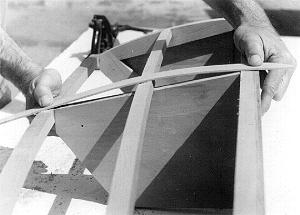
Fig. 9: The same area after fairing at the RUNNER SHEER #8. The simulated
planking will now lie flat or mate to all areas. |
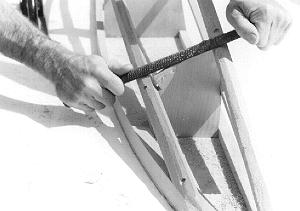 Fig. 10: One way to determine the amount of material to be
removed is to file a notch to the required bevel on the longitudinal at the
frames. In the forward area a wood rasp can be used to fair the RUNNER SHEER #8
and CHINE #10 simulaneously. Fig. 10: One way to determine the amount of material to be
removed is to file a notch to the required bevel on the longitudinal at the
frames. In the forward area a wood rasp can be used to fair the RUNNER SHEER #8
and CHINE #10 simulaneously. |
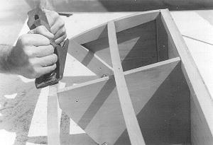 |
Fig. 11: In the aft section, excess material is removed with a hand plane.
All fairing should be done carefully to prevent humps or dips. |
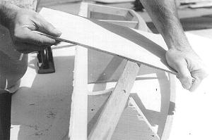 |
Fig. 12: Constantly checking with a length of plywood to simulate the
planking will help prevent errors. The planking must mate to all areas solidly
without gaps. |