 |
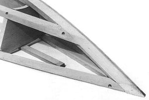
Fig. 13: The fairing completed in the forward portion of the runner
assembly. The STEM #7 has been faired to a point for the RUNNER SIDE PLANKING
#11 while the RUNNER SHEER #8 is almost triangular in shape. |
 |
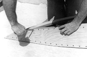
Fig. 14: The RUNNER SIDE PLANKING #11 is screwed in place after coating all
mating areas with glue. |
 |
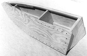
Fig. 15: The RUNNER SIDE PLANKING #11 is fitted oversize as shown. The only
area that must be fitted carefully now is that portion forward of FRAME #3
which will butt to the RUNNER BOTTOM #12. |
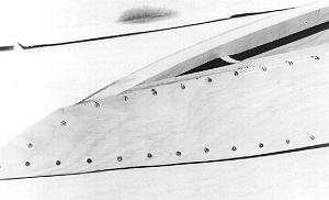
 Fig. 16: The RUNNER SIDE PLANKING #11 is shown after trimming
and fairing. Note the area forward that was carefully fitted to butt to the
RUNNER BOTTOM PLANKING #12 compared to the faired area aft of FRAME #3 where
the bottom will lap the side. Screws should be located lower here so as NOT to
interfere with fairing. Fig. 16: The RUNNER SIDE PLANKING #11 is shown after trimming
and fairing. Note the area forward that was carefully fitted to butt to the
RUNNER BOTTOM PLANKING #12 compared to the faired area aft of FRAME #3 where
the bottom will lap the side. Screws should be located lower here so as NOT to
interfere with fairing. |


 Fig. 16: The RUNNER SIDE PLANKING #11 is shown after trimming
and fairing. Note the area forward that was carefully fitted to butt to the
RUNNER BOTTOM PLANKING #12 compared to the faired area aft of FRAME #3 where
the bottom will lap the side. Screws should be located lower here so as NOT to
interfere with fairing.