Continued from WebLetter 12
Page 3 of 4
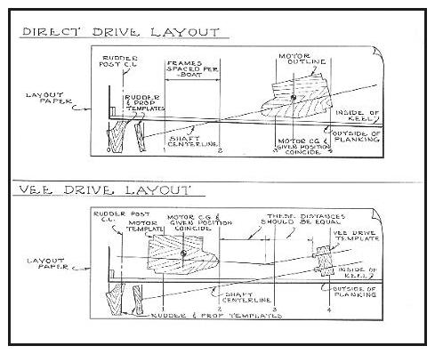
 Plate 35 - Shaft layouts for both in-line and vee
drive installations.
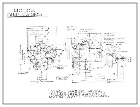
If you have a full size layout of the boat, or are building a boat from lofted lines, the layout for the engine installation can be readily made as illustrated by Plate 35. Failing this, it may be possible to make a full size layout from the designer's offsets, frame dimensions, or from full size patterns. The only areas of the hull that are important are the frames from the transom or stem forward, in way of the motor area, and the line of the keel or where the propeller shafts will intersect with the hull on twin screw boats. The outline templates representing the engine, propeller, and rudder may be cut from paper, cardboard, or wood. Motor dimensions can usually be obtained from scaled drawings available from the engine manufacturer or firm providing the conversion parts (see Plate 36 below). In some cases, full size drawings of motors are obtainable. If no dimensions or drawings are available, make a rough template taking dimensions directly from the motor, or sketch a rough outline in profile view. The engine crankshaft centerline is desirable for reference purposes and should be rather accurately pinpointed. The portion above this reference is desirable for checking heights and clearances, but may not be necessary in all cases. If the center of gravity (C.G.) of the motor is known or given, and necessary in the installation, mark this to the template. In lieu of rudder and propeller templates, the actual rudder or propeller can be used. If not available, templates for these can be made from dimensions furnished by the supplier's catalog. The width of the propeller can be estimated by dividing the pitch by the number of blades. For example, a propeller with a 12" pitch and three blades would have a width of 4". This is only an approximation, and if possible, the width or hub thickness of the propeller should be checked, or the supplier should have the information.
 Plate 36 - A typical marine
motor installation drawing available from most marine engine manufacturers
can be used to make the motor and shaft layout.
As shown by Plate 35 typical installation drawings are shown for both centrally located and vee drive straight shaft systems. Note that the point where the shaft passes through the boat may be readily found both on the inside and outside of the boat, assuming that the thickness of the hull at this point is fairly closely known. The shaft angle can be found by using a protractor, or figured from the chart in Plate 37.
In the case of the vee drive installation note the "jockeying" that can be done to the shaft angle in relation to the angle of the motor and the position or height of the vee drive above the inside of the hull or keel. The shaft angle should be as low as possible, and the angularity of the universals of the torque tube at a minimum. Shifting of the variables will determine the best possible position for the vee drive, and best suitable shaft angle. When the shafts of the vee drive have an angle between them, the problem is similar, but the angularity on the universals can be decreased more (see Chapter 4 on vee drives).
If the builder is opposed to making drawings, as many people are, there are other methods of determining the pertinent points in an installation. From a practical standpoint, the same could be accomplished during the construction of a boat prior to applying the planking. It is then physically possible to fit templated parts of the installation in the required position in the boat, noting the shaft angle and also the point that the shaft will project through the hull. In other words, the installation requirements are taken directly from the work, or "mocked-up", in place.